Background
I've been playing around with the Maxim DS18B20 digital temperature sensor. These are neat devices that provide a digital temperature, which means they provide an actual Celsius reading in digital form, with a pretty high level of accuracy, +/- 0.5C from -10C to 85C. They are also quite compact. Here is the typical TO92-3 form factor that the DS18B20 comes in.

Why not a thermistor connected to an ADC? Your microprocessor may not have an accurate enough or linear enough ADC to let you attain the desired temperature accuracy. In my case I'm using the Espressif ESP32.
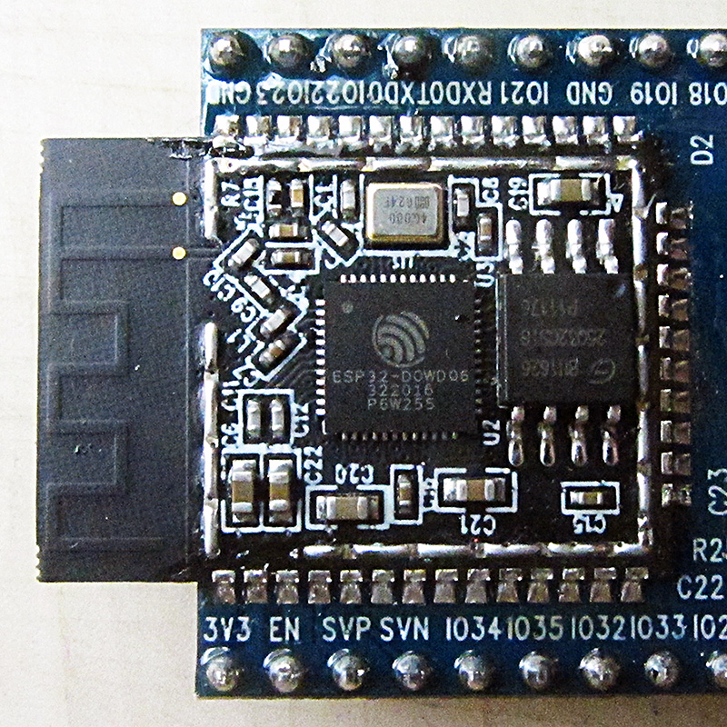
The ESP32 is a great processor but its ADC still needs some work. Code to linearize the ADC results was added earlier this year but the biggest missing piece is proper calibration of the ADCs vref. Without this the scaling of ADC values can vary by several percent. Good news is that factory calibration is possible and should be coming.
Thermistors also have a non-linear resistance over temperature.

From my research it looks like the Steinhart-Hart equation is a typical way to correct for this non-linearity. It may also be possible to use a lookup table with points at a number of temperatures.
With a digital temperature sensor you directly receive a temperature value. No ADC or ADC accuracy to worry about, no adjustment for non-linear resistance.
One downside is that the DS18B20 is a bit pricey. On Digikey they are $2.72 for a single piece and $2.10 at quantity 2000.
I'm using this assembly from DFROBOT (https://www.dfrobot.com/product-689.html). Having the sensor at the end of the cable means you can place the sensors in locations where you might not be able to reach if you put the TO92-3 component on a breadboard.

ESP32 1-wire support
David Antliff created a great library for interfacing to the DS18B20 on the ESP32. You can find it here in the esp32-ds18b20 repository on github.1-wire
The DS18B20 communicates using a 1-wire bus. 1-wire buses use a single wire for both power and communications. The "bus" in 1-wire buses indicates that more than one device can be on the same signal/power wire. The single signal/power wire is used for communication to/from the master and to/from the devices.The master, typically a processor, is in charge of communications and has to grant time slices for devices to respond. Due to the bus being shared between the master and a number of devices timing is important. Timing determines who, either the master or a device, has control of the bus.
The term '1-wire' is a bit misleading. You do typically need an additional wire for ground, so at a minimum you need two wires. I mention typical as it is possible to use an equipment chassis for the ground path.
Microprocessor ------- 1-wire bus ------- Device signal/power
       Ground --------------------------- Device ground
The DS18B20 also provides an optional dedicated power pin. Providing power to this mean means there isn't a concern about excessive communication depleting the energy stored in the device. In my configuration I had an extra wire available so I'm providing external power and using a three wire configuration.
Microprocessor ------ 1-wire bus ------ Device signal/power
  Power (3.3V) ------------------------ Device power
        Ground ------------------------ Device ground
CRC errors
With David's 1-wire library I was able to get the sensor working and reporting values in about an hour, including wiring the temperature cable. I started seeing these error messages pop up periodically, maybe once or twice a minute, when issuing temperature reads from the DS18B20 device every few seconds:E (10812382) ds18b20: CRC failed E (10815772) ds18b20: CRC failed E (10819162) ds18b20: CRC failed
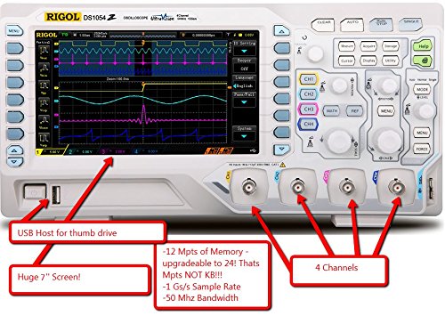
I recently purchased a Rigol DS1054Z digital oscilloscope. It's an excellent oscilloscope for hobby use and quite powerful. Low cost digital oscilloscopes have improved dramatically over the past several years. Features normally be available only in expensive commercial equipment are now available to the hobbyist for a few hundred dollars.
Reset and presence detection
After reading up on the 1-wire protocol and reviewing the scope traces I spotted something odd.
Here is a capture of the 1-wire presence detection. Presence detection is where the master is attempting to see if there are any 1-wire devices on the bus. A 'reset and presence detection' occurs before each communication from the master to DS18B20 so incorrect communications during this operation could be related to the CRC errors the library is reporting.


Here I've applied some colors. Green represents areas where the bus master (the ESP32 processor) is in control of the bus, and purple where the DS18B20 is in control of the bus. Note that they overlap in the area circled in white.
In this case the ESP32 is attempting to drive the bus to a high state, 3.3V, while the DS18B20 is attempting to pull it down to 0V.
This condition isn't fatal to either the device, the DS18B20, or master, the ESP32, evidenced by it occurring on my setup here for a number of days. The DS18B20 is designed to handle bus contention as it is possible to have a dozen 1-wire devices on the same bus and they sometimes do step on each other. The ESP32 likewise isn't affected here, in this case I have a series resistor limiting its current, effectively limiting how hard it can push/pull the voltage of that signal.
But what is going on there? Is this normal 1-wire behavior to have that contention? It turns out that it isn't required and the DS18B20 documents suggest that the master should release the bus.
Looking at the 1-wire ESP32 library, esp32-owb, I found this code in _reset():
        gpio_set_direction(bus->gpio, GPIO_MODE_OUTPUT);
        _us_delay(bus->timing->G);
        gpio_set_level(bus->gpio, 0);  // Drive DQ low
        _us_delay(bus->timing->H);
        gpio_set_level(bus->gpio, 1);  // Release the bus (NOTE: This does not release the bus)
        _us_delay(bus->timing->I);

        gpio_set_direction(bus->gpio, GPIO_MODE_INPUT); (THIS IS WHERE THE BUS IS RELEASED)
        int level1 = gpio_get_level(bus->gpio);
        _us_delay(bus->timing->J);   // Complete the reset sequence recovery
        int level2 = gpio_get_level(bus->gpio);
The orange line is where the master is trying to pull the bus high. The green line is where the master switches to input mode and stops driving the bus, this is where the bus is actually released.
If we alter this code release the bus at the correct location we get this code:
        gpio_set_direction(bus->gpio, GPIO_MODE_OUTPUT);
        _us_delay(bus->timing->G);
        gpio_set_level(bus->gpio, 0);  // Drive DQ low
        _us_delay(bus->timing->H);
        gpio_set_direction(bus->gpio, GPIO_MODE_INPUT); // Release the bus
        gpio_set_level(bus->gpio, 1);  // Reset the output level for the next output
        _us_delay(bus->timing->I);

        int level1 = gpio_get_level(bus->gpio);
        _us_delay(bus->timing->J);   // Complete the reset sequence recovery
        int level2 = gpio_get_level(bus->gpio);
Note that the green line was moved up above the orange line. We can see the effect this has from another scope trace:

After highlighting the master controlled area in green and the DS18B20 area in purple you can see that the two areas no longer overlap.
We've fixed the bus contention during the presence detection!
But I'm still seeing those CRC errors...
Read Time Slot
Lets's look at is the communication when the data and CRC are being sent. Devices on a 1-wire bus send data during a 'Read Time Slot' where the master initiates the transfer and the device fills in its data value.Here is a capture during data communication:
 |
| Read time slot with bus contention |
 |
| Colored version of read time slot with bus contention |
And after applying color per the 1-wire protocol specification you can see that the master and DS18B20 are driving the bus for quite a long time. Even though DS18B20 is able to pull the line to a logical low, < 0.8V, it isn't a good idea to have the master and DS18B20 working against each other.
Note that this issue is not resulting in data corruption. The master releases the line in advance of the time where the bus value is sampled. The little dip at the right hand side of the white circle is where the master has stopped driving the line. In addition the DS18B20 is able to pull the line low even as the master is attempting to drive it high. The voltage is a consistently a logical low throughout the communication of the bit.
 |
| Read time slot with minimal bus contention |
I've highlighted in white the fact that there is still a very small glitch. The level here, and the location in terms of time, aren't a concern, the master isn't going to read the value from the bus until much later in time.
The cause of this glitch is unavoidable. The bus master pulls the line low to tell the DS18B20 that it should respond with a 0 or 1 value by pulling the line high or low. When the master releases the line the external pull-up will pull the line high until the DS18B20 pulls the line either high or low. Because the timing cannot be precisely coordinated there will either be a gap or some overlap. The 1-wire protocol accounts for this overlap by having the master read the bus value after a period of delay where the bus can be released and the DS18B20 can cleanly signal a low or high value.
Conclusion
Bus contention should be avoided. Fortunately none of the issues found here should have affected 1-wire communications but unfortunately that means that these changes aren't likely to fix the CRC errors I was seeing. This is supported by the fact that I'm still seeing CRC errors at the same rate even after these fixes have been applied. I'm planning to continue debugging the source of the CRC issues.I've passed the bus contention improvements back to David Antliff so the 1-wire library can be improved. His libraries are well written and easy to use. This relatively minor bus contention issue is something easy to miss and it's present in the example pseudo-code provided by Maxim. I'm hoping it will be corrected in these libraries in the very near future.
The scope traces here are indicative of typical signal/bus contention issues. If you see a voltage that isn't logic high or logic low check to see that contention between devices isn't the cause. In some cases contention can cause devices to burn out due to excessive current sunk or sourced as the devices work against each other.
Comments
Post a Comment